

『Installation method of fire flowmeter』Related information(v cone flow meter|rotary gas meter|gallon meter|gear meter|metal tube rotameter|glass tube rotameter|nutating disk meter|transit time ultrasonic flow meter|wedge flow meter|pd meters|hydraulic flow meter|ultrasonic water flow meter|water flow meter|air flow meter|magnetic water flow meter|oxygen flow meter|gas flow meter|argon flow meter|air velocity meter|gasoline flow meter|fuel flow meter|ultrasonic water meter|digital water meter|nitrogen flow meter|solid flow meter|Oxygen tank flow meter|digital water flow meter|diesel fuel flow meter|steam flow meter|02 flow meter|compressed air flow meter|oil flow meter|liquid flow meter)
1. Installation location requirements for fire relief valves and flow meters
The installation location requirements for fire relief valves and flow meters are different and need to be understood separately. The core of the pressure relief valve is to protect the water pump and pipeline network, installed at the pump outlet; The core of a flowmeter is accurate measurement, which requires a stable fluid environment. 1. The installation position of the fire pressure relief valve is at the core position: it must be installed on the pipeline at the outlet of the fire pump, and as close as possible to the pump. Installation method: It is usually required to be installed horizontally to ensure that the internal valve disc can clear and move normally. Environmental requirements: It should be installed in a location that is easy to operate and maintain, avoiding installation in narrow or concealed areas. At the same time, mechanical damage should be avoided by setting up support and hanger brackets to reduce the impact of pipeline vibration and water hammer impact.
2. The installation position of the fire flowmeter should be at the core position: it must be installed in a position with a sufficiently long straight pipe section. The specific requirements are that the length of the upstream straight pipe section should be ≥ 10 times the pipe diameter, and the length of the downstream straight pipe section should be ≥ 5 times the pipe diameter.
. Environmental requirements: Keep away from equipment such as water pumps and valves that can cause fluid disturbances to ensure measurement accuracy. The installation location should be easy to observe, read, and maintain. At the same time, the installation point should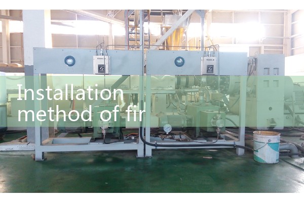
2. The correct method for installing a fire ultrasonic flowmeter is to select a straight pipe section with full fluid flow and smooth flow, ensuring that there are straight pipe lengths of 10 times and 5 times the pipe diameter upstream and downstream, avoiding flow disturbances such as valves and elbows, and staying away from interference sources such as pumps and frequency converters.
. Before installing the sensor, the surface of the pipeline needs to be polished smooth, coated with coupling agent, and fixed with fixtures. Depending on the diameter of the pipe, the V method (≤ DN100) or Z method (>DN100) should be selected for installation. Adjust the position to ensure that the signal intensity is greater than 60 and the transmission time is stable within the range of 100 ± 3. Finally, perform zero point calibration. The installation position should be preferably selected in the middle of the vertical or horizontal pipe section to avoid gas accumulation at the top of the pipeline or scale buildup at the bottom, which may affect the measurement. It is strictly prohibited to install on the highest point of the pipeline or on vertical pipes with free outflow. For non full pipe conditions, it should be installed in U-shaped pipe sections. Cast iron pipes and rusted steel pipes must be thoroughly inspected and polished to a metallic luster, while plastic pipes require the use of specialized coupling agents. There should be no air bubbles or sand particles between the sensor and the pipeline, and the clamping fixture should be moderately tightened to ensure good contact
 Hot Blog
 Related AD