

 Current position > News detail
『Rosemount flowmeter manual』Related information(v cone flow meter|rotary gas meter|gallon meter|gear meter|metal tube rotameter|glass tube rotameter|nutating disk meter|transit time ultrasonic flow meter|wedge flow meter|pd meters|hydraulic flow meter|ultrasonic water flow meter|water flow meter|air flow meter|magnetic water flow meter|oxygen flow meter|gas flow meter|argon flow meter|air velocity meter|gasoline flow meter|fuel flow meter|ultrasonic water meter|digital water meter|nitrogen flow meter|solid flow meter|Oxygen tank flow meter|digital water flow meter|diesel fuel flow meter|steam flow meter|02 flow meter|compressed air flow meter|oil flow meter|liquid flow meter)
1. Rosemount electromagnetic flowmeter 8732EM transmitter type digital adjustment!
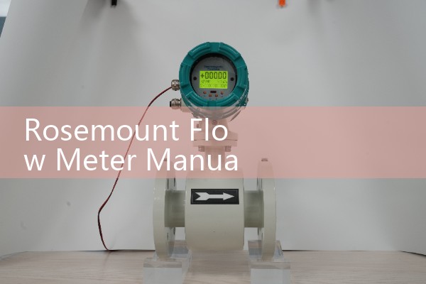
The digital adjustment steps for the Rosemount electromagnetic flowmeter 8732EM transmitter are a function used in factory calibration of the transmitter, and users usually rarely use this step.. Digital adjustment is only necessary when there is suspicion that the Rosemount 8732EM transmitter is inaccurate. The following is the detailed process for digital adjustment:
Firstly, the prerequisite for digital adjustment is that it can only be performed when the coil drive mode is set to 5 Hz and the nominal sensor calibration number is stored in memory. Performing digital adjustments without using the Rosemount 8714D calibration standard may result in inaccurate transmitter readings or error messages. If the message Digital adjustment failed appears, it indicates that no value in the transmitter has changed. At this point, simply disconnect and reconnect the power supply to the Rosemount 8732EM to clear this message.
II. Before changing any configuration parameters, make sure to record the original values of the nominal sensors with Rosemount 8714D calibration standard, so that the transmitter can return to the original configuration before resuming operation. If the settings cannot be restored to the original configuration, it will result in incorrect flow and accumulator readings. The following five parameters need to be changed/verified: Calibration number: 10000 Unit: ft/s (feet/second) PV URV (upper limit of primary variable range): 20 mA=30.00 ft/s PV LRV (lower limit of first variable range): 4 mA=0 ft/s Coil drive frequency: 5 Hz
III. Digital adjustment steps (if necessary) Set the circuit to manual
4. Precautions Before making numerical adjustments, please ensure that you have fully understood the operating instructions and safety precautions of the equipment.
. During the adjustment process, please follow the operating instructi